| Quoi de neuf ? Salutations Les mots de nous |
| Les membres Software Hardware Publish |
| Liens |
| Photos |
 |
 |
 |
| Visiteurs : |
ALTERNb |
| Dernière mise à jour : |
SKulpt W3D - Classic Amiga version
Introduction
sKulpt aims at being (someday J ) the modern reincarnation of the ancient but beloved Amiga 3D modeling and ray tracing software Sculpt Animate 3D / 4D by Eric Graham and Byte By Byte.
Sculpt was (and still is) a model for simplicity and ergonomy, and many pictures were drawn by it, in amateur and professional contexts.
Furthermore, it was cheap, although it packed many features and was almost bug-free.
Alas... It seems like Byte By Byte is out of business (since long on the Amiga market anyway), unreachable, and the source code for Sculpt was not released in open form.
I would still be using it nowadays if...
- Its modeling windows were compatible with RTG screens (Sculpt is restricted to PAL non-lace screens),
- It was compiled for the 68040 or the 68060, or even better the PPC, taking advantage of the orders of magnitude higher calculation speed of these processors over the 68000 and the 68020, the only two processors for which Sculpt is available on the Amiga,
- It used the 3D hardware available on the Amiga for a real-time preview,
- It enabled use of textures.
SKulpt will someday cover these features in a fully usable form, if I have enough spare time to finish it... You can help, since I provide the source.
At the moment, sKulpt is a project in development, yet supporting :
- RTG support (any screen compatible with Warp3D drivers)
- 060 and PPC versions (both compiled with StormC v3, waiting for StormC v4 w/GCC to have a good optimization). PPC version requiring WarpOS.
- use of 3D hardware (works well with both CyberVision 64/3D and B|CVisionPPC)
- use of textures (any image file format supported by your installed Datatypes).
I'd say that around 60 percent of its features are implemented and available. More are actually in the code. This is because I first developed sKulpt on the PC, with the scope of porting it back to the Amiga afterwards. Developing under Microsoft's Visual C++ v6 is much faster than under SAS/C, and when I started the project, I did not know about StormC, which I bought since !
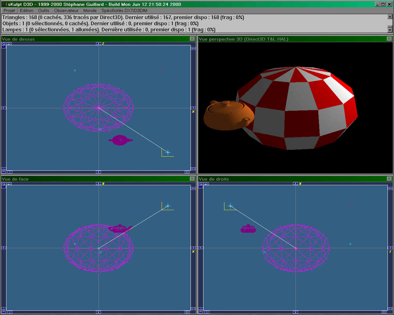
SKulpt thus also exists as a 32 bit Windows program, relying on the Microsoft DirectX v7 libraries (available under Windows 98 and 2000), with exactly the same features as the Amiga version (since both share most of the source code). If you know a bit of both Windows APIs and Amiga programming, give a look at the sources of both versions, you'll see how you can port something from Windows to Amiga (of course, it is easier if thought from the start). As an example, all dialog boxes on the Amiga version reside in the "gfx/sampler.res" file, which is a Microsoft Visual Studio's AppStudio resource editor compiled file, the very same which is linked into the PC executable. The dialog definitions are loaded from this file when required, and translated on the fly into GadTools windows and gadgets. Funny isn't it ? Furthermore, the dialog box handling code is the same also, and stub functions provide the Win32 emulation when necessary. We did this because setting up a dialog box with AppStudio is a child's play (even if limited in functionality), whereas GUI editors on the Amiga rely on much more complex concepts like fully resizable windows, font sensitive dialogs etc. which could simply not be shared with the PC. I would not like to have to keep up to date two different sets of GUI definitions.
Both versions live at the same level of functionality, one always having a slight advance over the other, depending on which platform I feel it will be easier to add a feature. Porting it to other platforms (Linux, BeOS, NextStep and MorphOS) could be done easily.
Requirements
To run sKulpt, you need :
- An Amiga (2000, 1200, 3000, 4000) with either a CyberVision 64/3D or a BlizzardVision PPC or a CyberVision PPC (the only Amiga graphics boards providing hardware 3D acceleration at the moment, respectively with the S3 Virge and the 3Dlabs Permedia2 chips), running at least OS3.0,
- A minimum of 8 megs of free memory
- Warp3D v3 installed and properly working with the provided test samples (WarpTest and Engine), either the 68K or the PPC version.
- A shell window to launch sKulpt, in which you will have set the stack to around 120 Kbyte ("stack 120000") before launching sKulpt. It will look in the "gfx" and "textures" subdirectories for files (gfx sub directory contents should not be modified otherwise sKulpt may not work).
You CAN'T run sKulpt if you don't have all the above
.Don't try to run sKulpt if the Warp3D samples provided in the Warp3D user archive don't fully work. Among these samples, WarpTest provides an easy GUI to test many Warp3D features.
The 060 version will run on any 32 bit 680x0 (from 020 to 060), and the PPC version will run on Blizzard PPC and Cyberstorm PPC boards (yet the 060 version is optimized for the 060 and the PPC version is optimized for the 604e).
Warp3D should run under Picasso96, but I encountered some problems with this setup, so I can only say it works well with CybergraphX (which I advise running in its latest release, 4.2p7).
Warp3D does not provide a software renderer, so if you have a PPC but no CV64/3D or B|Cvision PPC, you won't be able to run sKulpt. If you have a 030/50, 8 Megs of free RAM and a CV64/3D in an A2000, it will work (I can tell, as such a configuration is used as a test system for sKulpt).
If you would like to run sKulpt without a 3D accelerated board, write to HAAGE & PARTNER saying you want to write the software renderer for Warp3D, and be prepared to code a pretty complex but very interesting piece of software.
A word on 3D hardware acceleration, for the curious unaware. What's covered under these words of much hype is :
- a hardware triangle rasterizer, i.e. a chip to which you pass the screen coordinates of a triangle, and which will render it filled with either pixels taken from a texture, or with colors shaded between its 3 vertices, or flat, or a mix of these. This task alone is a giant step from software rendering, many times faster than what you can achieve with even the fastest processors, thus even faster with Amiga processors. To put it in simple words, this is a part of the Video chip, which is able to fill a triangle alone, and ways faster than what you could do with program code.
- a hardware Z-buffer, which will draw a pixel only if it is "closer to the screen" than the pixel which is already at the same coordinates in its z-buffer memory. This enables easy removal of hidden surfaces, with almost no programming. Here again, an equivalent software process is simply coded, but orders of magnitude slower. You can even set the compare function (less, equal, more, etc.), z-buffer span etc.
- other fancy features like clipping, fog emulation, various blending functions etc.
All these functions were available since many years, but only in expensive CAD workstations or high-end CAD-dedicated video boards. Thanks to Mr. Carmack and his Quake hit, these features, crucial in 3D game programming, came to the desktops in almost all PCs at affordable prices. One of the first chips implementing these features at a reasonable price was the S3 ViRGE, which is the heart of the CyberVision 64/3D (while completely outdated on the PC scene).
What is left to software (on the Amiga) is :
- transform : the process of taking absolute 3D coordinates for triangle vertices and converting them to screen coordinates through a pipe of matrices (bone combination matrices, camera space projection and 2D projection)
- lighting : determining the amount of R, G, B for each triangle vertex, taking in consideration (among other parameters) the contribution of each light in the scene to the lighting of the vertex, modulated by the distance between the light and the vertex. Spreading these colors to each pixel in the triangle is left to the hardware (which linearly interpolates vertex colors, a process called Gouraud shading).
As you may have heard, on the PC platform, modern graphics boards like nVidia's GeForce ® © J take these two functions into hardware, thus freeing the processor for other calculations. At the time of this writing, this is not the case on the Amiga.
Principles
SKulpt is a 3D scene editor, and an image / animation renderer.
The purpose of sKulpt is to enable one to draw 3D objects, set their respective positions, their appearance properties through association with materials, associate textures with materials, add lights, and render everything into an image. Additional animation features enable rendering a succession of images, between which the scene is modified (object or light movements etc.)
To use sKulpt, one must understand the following concepts :
- a scene is a collection of meshes, edges, vertices and lamps (plus animation objects)
- a mesh is a collection of triangles
- a triangle is defined by 3 vertices (points in space), and a material
- a material is defined by its lighting and texture properties
- an edge is a segment between two vertices. Edges only serve for creating complex shapes by extrusion or helix replication etc. They are not rendered in the 3D view, since they have no surface.
- a vertex is a single point, which may be part of 0 to n edges, and of 0 to n triangles. Like edges, vertices by themselves are not rendered in the 3D view, since they also have no surface.
Thus, the only things you will see in the 3D window are triangles, since vertices and edges don't define surfaces by themselves, so can't be rendered.
Various other considerations are taken into account in rendering, like face normals, blending etc., but for a quick introduction this is sufficient.
The process of creating a 3D object is the following :
- Create triangles,
- Define materials, maybe link textures to materials,
- Associate triangles and materials, and set their texture coordinates if the material is textured
- Set the camera and target position.
This is sufficient to create a 3D scene, which gets rendered as a 2D picture in the 3D view J
This process can be eased by the use of productive tools, like extrusion, curve filling, etc.
The work of vertex / edge / triangle setup is done in 3 2D windows (face, top and side view).
For a more detailed introduction, please give a look at the original Sculpt documentation, which I can't reproduce here for copyright reasons, or at the reference user's guide chapter in this document.
Quick features overview for the Sculpt-aware
Same menu structure as in Sculpt 3/4D, mostly same features at same place.
Able to load, view and rework Sculpt 3/4D scenes, except paths and object names. All the provided ".scene" sample scenes are actually original Sculpt 3D demo scenes. If you have a Sculpt scene which won't load in sKulpt, tell me.
Able to load / save its own binary file format (IFF ".sk3D", pretty fast).
Able to load / save Microsoft's DirectX X file format (".x") (not fully functional in the current release).
Modeling in 3 2D windows (top, face, side views) :
- top, face and right wireframe projection views, with the same gadgets as in Byte by Byte's Sculpt3/4D, providing grabber, panning, zooming in / out, vertex and triangle creation,
- real time volumic and lighted 3D perspective view, using Warp3D (Direct3D on the PC), updated as you modify your model or move target / observer or change face or material or lamp properties
Modeling with 5 cursors :
- main (blue cross), dragged by mouse left-click + move
- secondary 1 (small blue x), moved by shift-dragging
- secondary 2 (small blue +), moved by control-dragging
- observer (little white cross), moved by right-Amiga dragging (middle- + left-button dragging on the PC). You can also set the camera at the main cursor position with either 't' or the menu entry.
- camera (little white v), moved with right Alt dragging (right- + left-button dragging on the PC). You can also set the camera at the main cursor position with either 'o' or the menu entry.
A white line always links camera and target.
These ease triangle creation, which is available with :
- 3 selected vertices
- 3 cursors if there is not exactly 3 selected vertices
Vertex creation is made at main cursor location, either with the point gadget or with 'P' key.
Modeling with tools (not all available at the moment) :
- selector (either menu or 's'). Select all with '>'
- de selector (either menu or 'u'). Unselect all with '<'
- magnet (either menu or 'm')
- curve (either menu or 'c'. Finish a curve with 'q' after having added points with 'p')
- extruder (either menu or 'x')
- spline
- grabber (either menu or lower left gadget or 'g')
Release the current tool with either menu or the space bar.
Edit materials with 'm'.
Edit selected faces material association with 'f'.
Edit lamps with 'l'.
Reposition all windows with the ESC key.
All selecting, editing, transforming features of Sculpt 3/4D (not all available at the moment).
Able to draw 3D as solid, wireframe or vertices.
Very sophisticated mesh triangulation engine, based on the Triangle project, supporting holes, optimization and more.
User's reference
Introduction
SKulpt offers various flexible ways to do the same thing. For instance :
- To create a point, you can set the main cursor position (clicking the mouse anywhere in the 3 2D windows), then either select the "Edit > Add > Point" menu entry, or click on the "..." window gadget, or type 'p' on your keyboard,
- To move the camera, you can either drag (left-click + mouse move) it while pressing the Right-Amiga key, or set the main cursor position and select the "Environment > Define observer" menu entry, or (if you have a 3 button mouse) drag it with the middle button, or type the 'o' key
- And so on.
This chapter aims at giving you the purpose of the various sKulpt commands, be they entered by menu entries, window gadgets, keys. SKulpt embeds various ways to do the same thing, as this was the case with the original Sculpt software, so that you can find the way which is most convenient to you. In the future, this concept will be pushed further, through introduction of customizable menus, a customizable graphical pad which will enable gathering your most useful commands, accessible through small icons, scripting features, with either the embedded sKulpt scripting language (similar to the original Sculpt), and AREXX availability of variables and commands.
This chapter then demonstrates these commands in action in simple scene creations.
If you feel it should be organized or illustrated in a different way, don't hesitate, tell me.
The GUI
The GUI stands for "Graphical User Interface". This chapter is meant to explain its principles to unfamiliar users.
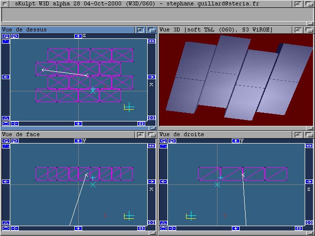
It is what you see on your screen when running sKulpt.
The GUI is made of the following entities :
- 5 main windows : three 2D windows (top, face and right views), one 3D window, one trace window,
- a number of dialog boxes, which are windows dedicated to a particular function, shown only while using this function,
- a menu, which enables command selection with the mouse.
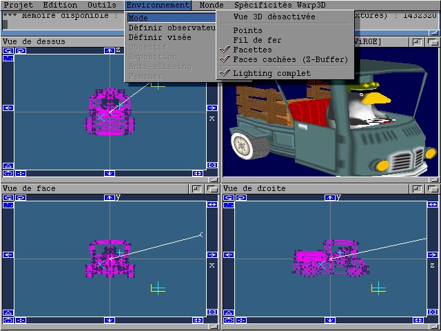
All this is shown above (here in a 640x480x15 screen, but you can use whatever screen mode you want provided you have enough free graphics board video memory) :
Contents of the 2D windows
The 2D windows represent the projection of your virtual 3D space along the 3 planes of a Cartesian coordinate system defined this way :
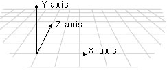
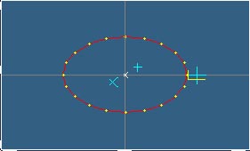
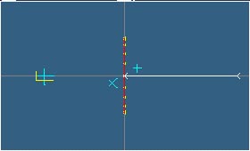
The face view shows the projection of all objects on the X/Y plane. The top view shows the projection of all objects on the X/Z plane. The right view shows their projection on the Z/Y plane.
If I add a circle to my scene, which is centered on the origin, and turns around the Z axis (let's say Z), this circle is in the X/Y plane, and the 3 2D views will show like this :
- face (X/Y) view :
- top (X/Z) view :
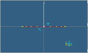
- right (Z/Y) view :
In the 2D windows, you also see above :
- the main cursor, which is the largest cyan cross surrounded by a yellow L shape. This shape materializes the influence zone of the current tool (when applicable). For instance, if the selector tool is the current tool, all vertices falling in the influence zone while moving the cursor will be selected. When a tool is selected, its reminding letter is present near the main cursor (it will be a 'S' for the selector tool).
- The two alternate cursors (small cyan X and cross). These alternate cursors ease the process of triangle creation, as if you hit the "create triangles" gadget or menu command, and there are no selected vertices, the system will create a triangle between the main and alternate cursors.
- The camera and view target (two white small V's) always linked by a white line
- The axes of the Cartesian coordinate system (gray lines). To remember which are the axes (X, Y, Z) of the 2D window you're looking at, they are indicated in the dark blue border of the window.
These essential elements can fall in a non-visible space area, since when you pan or zoom in, they don't move in space. To expose them, either zoom out, or pan, or center the views on the main cursor (see this later).
Apart from these essential elements, the objects you create in your scenes display as follow :
- Vertices (points in space) display as dots, which can be either black (not selected), or yellow (selected)
- Edges (lines between 2 vertices) always display red
- Triangles (between 3 vertices) display either pink or green (only one will be green, the one you currently work on when editing its material properties)
- Lamps display as small red V's, and one in the scene may display green, the one you currently work on when editing light properties
This is all what can be seen in the inner region (light blue delimited by white rectangle) of the 2D windows.
To illustrate this, here is a face view of 3 triangles, 5 edges and 2 lamps. A few vertices are selected (yellow) :
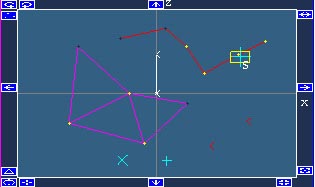
On this picture, you can also discover the window gadgets. They are the small icons taking place in the dark blue border surrounding the inner window region. Their functions are described in a further chapter.
We are done with 2D windows.
Contents of the 3D window
The 3D window will display the perspective view of the scene, seen from the camera position, looking at the target position.
What gets actually drawn is only the triangles (since they are the only basic entities to define a visible surface, as points and edges don't).
Triangles get drawn according to :
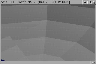
- Their presence in the clipped view pane. As for the 2D windows, the 3D window only represents a part of the 3D space, projected in camera space. As with a real camera, everything not in the field of vision you just don't see. With sKulpt there is one more restrictions : triangles too close to the camera are not drawn (this is due to technical restrictions of underlying drivers, which tend to crash when drawing too close and large triangles). This enables a handy feature : when you come very close to convex objects, you can "see inside" as the closest faces of these objects are just not drawn, here is an example with a sphere :
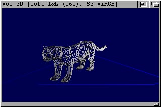
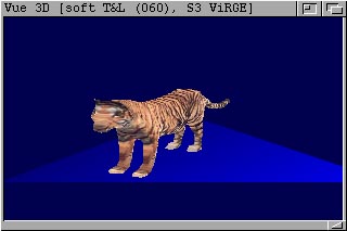
- Their associated material, which cans either be flat or textured. Material properties are edited with appropriate dialog boxes, in which you define the color and texture material properties, with semantics identical to those of Microsoft's DirectX 7 (tech note : this is due to the fact that Warp3D does not provide any concept in the fields of lighting and materials, so as sKulpt is also developed on the Microsoft Direct 3D Immediate mode v7, I chose to port these concepts to the Amiga, as they suit well the purposes of both fast hardware assisted pre-rendering, and ray tracing). Material properties detail a material's diffuse reflection, ambient reflection, light emission, and specular highlighting characteristics. Material properties affect the colors SKulpt uses to rasterize polygons that use the material. Each of the properties is described as an RGBA color that represents how much of the red, green, and blue parts of a given type of light it reflects, and an alpha blending factor (the alpha component of the RGBA color). The material's specular property is described in two parts: color and power. For more information, see "Color Values for Lights and Materials" in the Microsoft DirectX 7 SDK documentation (the end of this paragraph is a reworked excerpt of it). Diffuse and Ambient Reflection properties describe how a material reflects the ambient and diffuse light in a scene. Because most scenes contain much more diffuse light than ambient light, diffuse reflection plays the largest part in determining color. Additionally, because diffuse light is directional, the angle of incidence for diffuse light affects the overall intensity of the reflection. Diffuse reflection is greatest when the light strikes a vertex parallel to the vertex normal. As the angle increases, the effect of diffuse reflection diminishes. The amount of light reflected is the cosine of the angle between the incoming light and the vertex normal. Ambient reflection, like ambient light, is non directional. Ambient reflection has a lesser impact on the apparent color of a rendered object, but it does affect the overall color, and is most noticeable when little or no diffuse light reflects off the material. A material's ambient reflection is affected by the ambient light set for the scene. Diffuse and ambient reflection work together to determine the perceived color of an object, and are usually identical values. For example, to render a blue crystalline object, you would create a material that reflected only the blue component of diffuse and ambient light. When placed in a room with a white light, the crystal appears to be blue. However, in a room that has only red light, the same crystal would appear to be black, because its material doesn't reflect red light. Emission can be used to make a rendered object appear to be self-luminous. The Emissive property is used to describe the color and transparency of the emitted light. Emission affects an object's color and can, for example, make a dark material brighter and take on part of the emitted color. You can use a material's emissive property to add the illusion that an object is emitting light, without incurring the computational overhead of adding a light to the scene. In the case of the blue crystal, the emissive property could be handy if you wanted to make the crystal appear to light up, but not actually cast light on other objects in the scene. Remember, materials with emissive properties don't actually emit light that can be reflected by other objects in a scene. To achieve this effect, you would need to place an additional light within the scene. Specular Reflection creates highlights on objects, making them appear shiny. You establish the color of the specular highlights by setting the specular property to the desired RGBA color—the most common colors are white or light gray. The values you set in the Power property control how sharp the specular effects are. Specular highlights can create dramatic effects. Textures are bitmaps mapped to the triangles, like if they were painted onto them. For instance, in the following picture, you see the same scene, left rendered as wireframe to show the triangles, and right rendered as full faces. It displays a textured tiger standing on a flat blue Gouraud shaded triangle (light is on the right of the scene) :
- Their light exposure. In all cases, sKulpt applies Gouraud shading. When sKulpt renders a polygon using Gouraud shading, it computes a color for each vertex by using the vertex normal and lighting parameters. Then, it interpolates the color across the face of the polygons. The interpolation is done linearly. For example, if the red component of the color of vertex 1 is 0.8 and the red component of vertex 2 is 0.4, utilizing the Gouraud shading mode and the RGB color model, the lighting module would assign a red component of 0.6 to the pixel at the midpoint of the line between these vertices. The following figure demonstrates Gouraud shading. This teapot is composed of many flat, triangular polygons. However, Gouraud shading makes the surface of the object appear curved and smooth :

Remark 1 : in the current pre-version, the specular component of both materials and lights are not taken into account by the lighting engine.
Remark 2 : in the current pre-version, the normals at each vertex are calculated per triangle (and not globally), thus the shading is ok inside the triangle, but the same vertex shared by another triangle will have a different normal, thus the shading will not be smooth across triangles.
Remark 3 : in the current pre-version, only the point light type is implemented. Directional and spot will follow.
Remark 4 : in the current pre-version, the range parameter of lights is not taken into account, thus the attenuation is computed whatever be the distance between a lamp and a vertex.
SKulpt offers two lighting models : the first is fast and inaccurate, considering there is only one light, which is located at the same place as the camera. This is for fast preview. The second is a complete lighting module conforming to a large part of the specifications of the Direct3D v7 lighting module. Light sources in Direct3D emit diffuse, ambient, and specular colors as distinct light components that factor into lighting computations independently of each other. SKulpt determines the distance between a light source and a vertex being lit by taking the magnitude of the vector that exists between the light's position and the vertex : D == ||VL||. D is the distance being calculated, V is the position of the vertex being lit, and L is the light source's position. If D is greater than the light's range property, no further attenuation calculations are made and no light effects from the light are applied to the vertex. If the distance is within the light's range, SKulpt then applies the following formula to calculate light attenuation over distance for point lights and spotlights (directional lights don't attenuate) : A = 1 / (attn0 + D x attn1 + D² x attn2). In this attenuation formula, A is the calculated total attenuation and D is the distance from the light source to the vertex. The dvAttenuation0, dvAttenuation1, and dvAttenuation2 values are the light's constant, linear, and quadratic attenuation factors as specified by the properties of a light object. The system normalizes D to be within the range [0.0,1.0], where 0.0 indicates no light at the vertex, and 1.0 indicates full light intensity at the vertex. The constant, linear and quadratic attenuation factors act as coefficients in the formula—you can produce a wide variety of attenuation curves by making simple adjustments to them. You could set the constant attenuation factor to 1.0 to create a light that doesn't attenuate (but will still be limited by range), or you can experiment with different values to achieve various attenuation effects. The attenuation formula used by SKulpt computes an attenuation value that typically ranges from 1.0 at the light source to 0.0 at the maximum range of the light. The attenuation value is multiplied into the red, green and blue components of the light's color to scale the light's intensity as a factor of the distance light travels to a vertex. After computing the light attenuation, SKulpt should also consider spotlight effects (if applicable), the angle that the light reflects from a surface, as well as the reflectance of the current material to come up with the diffuse and specular components for that vertex.
In the current release, the complete lighting process is the following (will evolve to get more complete) :
step 1 : calculate the 3 vertex normals
step 2 : preset the RGB color values for the 3 vertices to the following sum : (material emissive + material ambient * ambient light) (for the Alpha component, only the Diffuse is taken into account, and it is the same for the 3 vertices)
step 3 : for each lamp, calculate its contribution to vertex lighting :
step 4 : calculate the vertex Gouraud shading weighting factors : cosine(vector(lamp-vertex), vertex normal)
step 5 : calculate the 3 lamp / vertex distances
step 6 : calculate the 3 attenuation factors
step 7 : calculate the non-attenuated lamp's RGB diffuse contributions (lamp * material)
step 8 : calculate the non-attenuated lamp's RGB ambient contributions (lamp * material)
step 9 : accumulate into the RGB color values for the 3 vertices the lamp's attenuated diffuse and ambient contributions
step 10 : top all calculated RGB's to 1 (so not to overflow the video RAMDAC)
Contents of the trace window
The trace window displays either informative messages, or error messages (if you ask for something impossible like creating a triangle with only 2 vertices, or if sKulpt encounters an internal error).
All these messages have a unique number, which you should mention when you report strange situations or bugs to the author.
The trace window is not refreshed when overdrawn, to save graphics memory. Thus if you really care for the traces, either look in the shell window in which you started sKulpt (which holds a copy of all traces), or set the window positions in such a way that the trace can hold what you are looking after. I suggest using a console manager like KingCon in the shell, so that you can review the traces in the review buffer. You can even copy/paste all traces since startup in your eMails when reporting something to me.
Window manipulation
Window manipulation conforms to the Amiga standards. Windows have front/back gadgets, a title / drag bar, a size gadget. To have more information on this topic, please browse your Workbench documentation.
Menu entries
In the following table, all white menu entries are not available yet.
|
Menu |
Menu entry |
Sub items |
Function |
Notes |
|
Projet |
Charger |
Scène Sculpt 3D / 4D |
Load a genuine Sculpt 3/4D scene |
|
|
Scène sKulpt D3D/W3D |
Load a new sKulpt file format scene |
|
||
|
Scène DirectX |
Load a Microsoft DirectX text file format scene |
|||
|
Image |
|
|
||
|
Objet |
|
|
||
|
Script |
|
|
||
|
Objet nommé |
|
|
||
|
Prise de vue |
|
|
||
|
Animation |
|
|
||
|
Fonte |
|
|
||
|
Plugin |
|
|
||
|
Sauver |
Scène Sculpt 3D / 4D |
|
|
|
|
Scène sKulpt D3D/W3D |
Save a new sKulpt file format scene |
|
||
|
Scène DirectX |
Save a Microsoft DirectX text file format scene |
|||
|
Image |
|
|
||
|
Objet |
|
|
||
|
Objet nommé |
|
|
||
|
Montrer |
Image |
|
|
|
|
Animation |
|
|
||
|
Preview |
|
|
||
|
Décharger |
Image |
|
|
|
|
Animation |
|
|
||
|
Preview |
|
|
||
|
Fonte |
|
|
||
|
Plugin |
|
|
||
|
Batch |
|
|
|
|
|
A propos |
|
Show About requester |
|
|
|
Résumé |
|
Show used vertex / edge / triangle / lamp slots & frag |
||
|
Quitter |
|
|
|
|
|
Edition |
Sélectionner |
Tout sauf lampes |
Select all vertices (but no lamp) |
|
|
Noeuds connexes |
Select all vertices connected to already selected vertices |
|
||
|
Noeud indiqué |
Select vertex closest to main cursor |
|
||
|
Lampe indiquée |
Select lamp closest to main cursor |
|
||
|
Toutes les lampes |
Select all lamps |
|
||
|
Noeuds par nom |
|
|
||
|
Arête indiquée |
|
|
||
|
Spline indiquée |
|
|
||
|
Trajectoire indiquée |
|
|
||
|
Inverser la sélection |
Unselect selected and select unselected vertices |
|
||
|
Désélectionner |
Tout |
Unselect all |
|
|
|
Noeud indiqué |
Unselect vertex closest to main cursor |
|
||
|
Lampe indiquée |
Unselect lamp closest to main cursor |
|
||
|
Toutes les lampes |
Unselect all lamps |
|
||
|
Noeuds par nom |
|
|
||
|
Arête indiquée |
|
|
||
|
Inverser la sélection |
Unselect selected and select unselected vertices |
|
||
|
Effacer |
Tout |
Erase everything |
|
|
|
Noeud indiqué |
Erase vertex closest to main cursor |
|
||
|
Noeuds sélectionnés |
Erase selected vertices |
|||
|
Arêtes sélectionnées |
Erase selected edges |
|||
|
Triangles sélectionnés |
Erase selected triangles |
|||
|
Lampe indiquée |
Erase lamp closest to main cursor |
|
||
|
Lampes sélectionnées |
Erase selected lamps |
|
||
|
Toutes les lampes |
Erase all lamps |
|
||
|
Noeuds par nom |
|
|
||
|
Spline indiquée |
|
|
||
|
Trajectoire indiquée |
|
|
||
|
Modifier |
Matériaux |
Edit material properties |
||
|
Facettes |
Edit selected triangle material associations |
|||
|
Lampes |
Edit lamp properties |
|
||
|
Origine locale |
|
|
||
|
Noeud de trajectoire indiqué |
|
|
||
|
Tangente de trajectoire indiqué |
|
|
||
|
Prise de vue |
|
|
||
|
Transformer |
Agrandir / réduire |
Expand / reduce size of selection |
||
|
Remplir |
Fill closed curve with triangles |
|||
|
Subdiviser |
Subdivide each selected triangle into 3 triangles |
|
||
|
Unslice |
|
|
||
|
Symétrie |
|
|
||
|
Répliquer sur hélice |
Replicate selection along helix |
|||
|
Répliquer sur spline |
|
|
||
|
Répliquer sur trajectoire |
|
|
||
|
Lisser les noeuds sélectionnés |
Smooth vertex normals of selection across triangles |
|||
|
Dé-lisser les noeuds sélectionnés |
Un-smooth normals : come back to per-triangle normals |
|
||
|
Montrer la trajectoire |
|
|
||
|
Cacher les noeuds sélectionnés |
Hide (in 2D & 3D) the selection |
|
||
|
Révéler les noeuds cachés |
Un-hide all hidden vertices, edges & triangles |
|
||
|
Repositionner les fenêtres |
Reset all window positions |
|
||
|
Auto texture mapping |
Planaire best fit |
|
|
|
|
Planaire XY |
|
|
||
|
Planaire YZ |
|
|
||
|
Planaire XZ |
|
|
||
|
Planaire libre |
|
|
||
|
Cylindrique best fit |
|
|
||
|
Cylindrique X |
|
|
||
|
Cylindrique Y |
|
|
||
|
Cylindrique Z |
|
|
||
|
Cylindrique libre |
|
|
||
|
Sphérique best fit |
|
|
||
|
Sphérique XY |
|
|
||
|
Sphérique YZ |
|
|
||
|
Sphérique XZ |
|
|
||
|
Sphérique libre |
|
|
||
|
Ajouter |
Clône de la sélection |
Add a clone of the selection, select it, set grabber tool |
|
|
|
Point |
Add a vertex under the main cursor |
|
||
|
Arête ou triangle |
Add an edge or triangle |
|||
|
Sphère |
Add a sphere |
|||
|
Hémisphère |
Add an hemisphere |
|||
|
Tore |
Add a torus |
|||
|
Boing ball |
Add a boing ball |
|||
|
Cube |
Add a cube |
|||
|
Prisme |
Add a prism |
|||
|
Disque |
Add a disk |
|||
|
Cercle |
Add a circle |
|||
|
Cylindre |
Add a cylinder |
|||
|
Tube |
Add a tube |
|||
|
Cône |
Add a cone |
|||
|
Chaîne de caractères |
|
|
||
|
Lampe |
Add a lamp |
|
||
|
Coller |
Curseur sur noeud le plus proche |
Snap cursor onto closest vertex |
|
|
|
Curseur sur centre de la sélection |
Snap cursor onto center of selection |
|||
|
Curseur sur barycentre |
|
|
||
|
Curseur sur grille |
Snap cursor on closest grid cross |
|||
|
Noeuds sélectionnés sur grille |
|
|
||
|
Noeuds connectés sur sphère |
|
|
||
|
Noeuds sélectionnés sur plan |
|
|
||
|
Nommer |
Noeuds connectés |
|
|
|
|
Trajectoire indiquée |
|
|
||
|
Lampe indiquée |
|
|
||
|
Grille |
Grille |
Activate the grid |
||
|
Pas |
Set grid step |
|
||
|
Coordonnées |
|
Toggle show / hide coords in the 2D windows |
|
|
|
Outils |
Aucun |
|
Activate no tool |
|
|
Sélecteur |
|
Activate selector tool |
||
|
Désélecteur |
|
Activate unselector tool |
||
|
Aimant |
|
|
|
|
|
Courbe |
Courbe |
Activate curve tool |
||
|
Finir |
Finish current curve |
|||
|
Extrudeur |
|
Activate extruder tool |
||
|
Spline |
|
|
|
|
|
Pince |
|
Activate grabber tool |
||
|
Environnement |
Mode |
Vue 3D désactivée |
Stop refreshing the 3D view (to speed up things) |
|
|
Points |
Show only triangle vertices in 3D view (lit, textured) |
|||
|
Fil de fer |
Show only triangle edges in 3D view (lit, textured) |
|||
|
Facettes |
Show full triangles in 3D view |
|
||
|
Faces cachées (Z-Buffer) |
Toggle activate hidden triangle removal with Z-buffer |
|
||
|
Lighting complet |
Toggle fast / full lighting engine |
|
||
|
Définir observateur |
|
Set camera position at main cursor |
|
|
|
Définir visée |
|
Set view target position at main cursor |
|
|
|
Objectif |
Normal |
|
|
|
|
Grand angle |
|
|
||
|
Télé |
|
|
||
|
Spécial |
|
|
||
|
Exposition |
Automatique |
|
|
|
|
Manuelle |
|
|
||
|
Anti-aliasing |
Aucun |
|
|
|
|
Bon |
|
|
||
|
Très bon |
|
|
||
|
Dithering |
|
|
||
|
Pencher |
|
|
|
|
|
Monde |
Ciel |
|
|
|
|
Sol |
|
|
|
|
|
Illumination globale |
|
Set global scene ambient lighting properties |
||
|
Spécificités Warp3D |
Optimisation vitesse / qualité |
|
Warp3D hinting |
|
|
Renderstate |
Transparence alpha blending |
|
|
|
|
Eclairage spéculaire |
|
|
||
|
Antialias |
|
|
||
|
BackFace culling mode |
None |
|
|
|
|
CW |
|
|
||
|
CCW |
|
|
||
|
Timedemo |
|
Run timedemo 1 |
Notes
- The loader of Sculpt original files does not load paths nor name hierarchies. Everything else is loaded (vertices, edges, triangles, lamps, observer & target position etc.). The loader does not erase existing entities in memory, but rather adds the contents of the file to the existing scene. All dimensions of objects in the file are scaled to fit within the current window dimensions. At the moment, sKulpt is not able to save original Sculpt files.
- The loader for ".x" DirectX object files does not load animation sets. All hierarchies are melted into the scene (i.e. you loose mesh / frame decomposition). The X loader does not support binary files, but only the text variant. If you want to load binary X files, please use the converter provided by Microsoft to convert them to text files. The X loader does not support pre-defined meshes and materials then referenced by their names (although this feature is often used in X files). This will be available in later releases, as well as a converter from animation sets into sKulpt paths. Please note that everything is erased prior to loading an X file, which is a different behavior from the original Sculpt loader. The native sKulpt format (".sk3d") loader acts as the X file loader, that is it erases all before loading. The X file format does not include camera / target / lamp definitions. Thus, camera / target location is not affected by loading an X file, and you may have to add lamps to "see something" in the 3D window after loading an X file.
- The saver for ".x" DirectX object files is far from complete, it is just a quick hack which should generate files that can be loaded with the Xfile viewer on the PC side. The saver does not generate files that can then be re-read by sKulpt (it will come later). At the moment, the format of choice (and the only format indeed) to load and save scenes is the native sKulpt format, ".sk3d" (which is an IFF format btw).
- The "Résumé" option puts the number of vertices, triangles, edges, lamps, materials etc. present in the scene. As sKulpt works with static tables, these tables may fragment as you delete entities, and in this case the "frag %" will not be 0 for the various entities. If you want to "garbage collect", or reorganize the tables to speed up things, you may enter the "!" command, which will do this automagically for you.
- Erasing vertices will also erase the edges or triangles which the vertices were part of.
- Erasing edges will leave the vertices untouched.
- Erasing triangles will leave the vertices untouched.
- Edit materials brings the following requester to the screen, leaving you play with the various attributes of the materials :
- Edit Faces will bring the following requester :
- The expand / reduce command will bring the following requester :
- The Fill command invokes the mesh triangulator. You must select a set of closed curves prior to invoking this command. The triangulator will try to arrange a set of triangles which fit in the curves, which are defined by vertices of the curves. This helps creating arbitrary shapes.
- The Replicate on helix command is also very powerful. It enables quick creation of translated AND / OR rotated clones of the selection.
- The smooth / unsmooth faces command is only working in the PC version by now. I am not certain how I will implement this on the Amiga, Warp3D being unaware of normals (in other words, I have to handle per vertex normal calculation by myself L ).
- This command will do nothing if there are neither 2 nor 3 selected vertices. Otherwise it will add an edge (2) or a triangle (3).
- This command will add a sphere, bringing a requester in which you can set the number of slices. The revolution axis is normal to the 2D window which was active when you invoked the command.
- Same as above, for an hemisphere.
- Same as above, for a torus.
- The boing ball has its properties pre-defined.
- N/a
- The prism is a cone with 4 vertices at its base. The revolution axis is normal to the 2D window which was active when you invoked the command.
- A requester asks for the number of slices. The revolution axis is normal to the 2D window which was active when you invoked the command.
- Same as above.
- Same as above.
- Same as above.
- Same as above.
- The main cursor will be centered to the unweighted average center of the selection.
- The main cursor will be centered to the closest grid step.
- This command is a toggle for grid activation. Grid introduces steps for the cursor locations, in both X/Y/Z axes. It helps creating vertices which are part in multiple triangles, for regularly shaped objects. Note that sKulpt has a smart feature which determines if it should consider two vertices as the same and when to do so.
- The selector tool is reminded by an 'S' next to the main cursor. Its influence zone is the yellow square around the main cursor.
- Same as above. The unselector's letter is 'U', and the influence zone is black.
- The curve tool lets you create free connected edge suites, otherwise named as curves. To create a point in the current curve at the current main cursor location, press 'p' or click the '…' window gadget. To finish the curve without closing it, simply select no tool (or press space). To finish the curve closing it to its first point, press 'q' or select "curve > finish". Take care to what is selected at the end before extruding or grabbing.
- See above.
- The extruder tool creates a clone of the selection, linked to the selection, selects the clone, and selects the grabber tool. When you then drag the main cursor, you will see an elevation of your original selection. To unselect the grabber tool, either press space or select the "Tool > none" menu command, or click on the grabber icon (the lower left 2D window gadget).
- The grabber tool lets you move all the selected vertices (the edges and triangles will follow). To unselect the grabber tool, either press space or select the "Tool > none" menu command, or click on the grabber icon (the lower left 2D window gadget). Take much care in what is actually selected when you use the grabber tool (even what you don't see because of panning and zooming). There is currently no way to put things in their original location. This also applies to the extruder tool, which is a special form of the grabber.
- The show points or edges commands let you reduce the time necessary to update the 3D view, by rendering only the vertices or triangle edges. It is also a creative tool. See the tiger sample above. Note : on the Permedia2 chip, the points and lines are fully textured, while on the ViRGE chip, the points and lines are only Gouraud shaded.
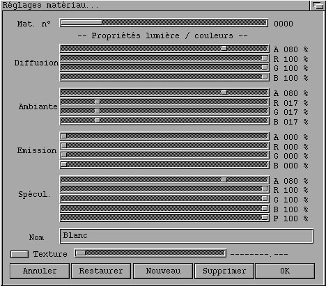
The top slider enables choosing the material you are working on. The first 5 materials (# 0 to 4) can not be deleted. Apart from this, all materials can be fully edited.
The Diffusion sliders let you adjust the RGBA properties of diffusion light properties for the material. See the lighting engine for additional info, and play with this to discover its use. Note that diffuse properties only show under light exposure, apart from the A which defines the A for the whole triangle.
The Ambient sliders let you play with the RGBA properties. They define the way the object "exposes" the ambient light definition made with the "Monde > Illumination globale" menu.
The Emission properties define the way the faces will emit light, i.e. they will seem lighted from the inside.
The Specular properties define the way the faces will "shine".
Notes : at the moment, the A components of Ambient, Emission and Specular are ignored. The Specular properties are also ignored.
The Name is the material name, which you can fully edit up to 80 char.
The Texture radio button and slider will let you choose whether this material is textured or not, and which texture will be mapped.
The OK button lets you validate all your changes. The Annuler (cancel) button will let you cancel the changes you made on the current material and close the requester. The Restaurer (restore) button will let you cancel the changes made on the current material without closing the requester. The Nouveau (new) button will let you duplicate the current material into a new one. The Supprimer (delete) button will let you delete the current material.
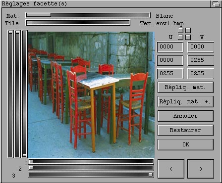
The purpose of this dialog is to enable you to choose which material is applied to the selected faces, and if the material is texture mapped, how the triangles project onto the texture.
When you enter this dialog, both the 2D and the 3D views get redrawn, and the triangle face on which you are currently working is outlined with a green line.
You can go to the 2D windows to move the target / camera while editing faces, so that you can always pick the best point of view.
In the dialog, the "<" and ">" let you navigate among the selected faces.
The top slider lets you choose the material to apply to the current face.
If the material is texture mapped, you will see the texture image drawn (like the above).
You can set the U/V (texture projection coordinates) for each of the 3 triangle vertices with the 1, 2, 3 horizontal & vertical sliders.
You can also premap the triangle to one of the 4 corners of the texture using the 4 small buttons above the U/V coordinates. These buttons cycle through the various combinations of 3 vertices to 3 texture corners.
The replicate button will spread the current face settings to all the selected faces, without affecting the destination face's U/V.
The replicate + button will also affect the U/V.
The OK button closes the dialog.
The other controls are not active at the moment.
Edit Lamps will bring the following requester :

This will let you edit the lamp properties. If there is no lamp in the scene, you won't have access to this requester. Otherwise, you can choose the lamp to edit using the top slider. The currently edited lamp gets drawn in green in the 2D windows.
The Diffuse / Ambient / Specular RGBA properties speak for themselves, give a look at the lighting engine chapter.
The other properties are lit / unlit, lamp type (point / spot / directional), the 3 distance attenuation coefficients, the range, falloff, teta and phi parameters.
In the current release, the spot / directional types are not implemented, and the range, falloff, teta and phi parameters are ignored.
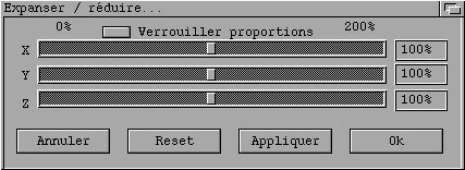
These commands only apply to the selected entities. The X/Y/Z factors speak for themselves ; the top radio button lets you lock the proportions. The Apply / reset buttons let you either apply the changes to the selection, or come back to the original settings, without closing the dialog. The OK / Cancel buttons do the same, closing the dialog.
Here is a curve before and after triangulation :
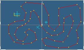
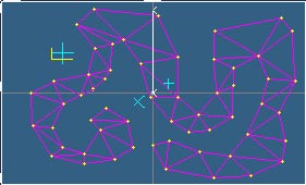
This is a very powerful feature, saving hours of work, particularly combined with extrusion. Here is the above triangulated curve extruded a bit :
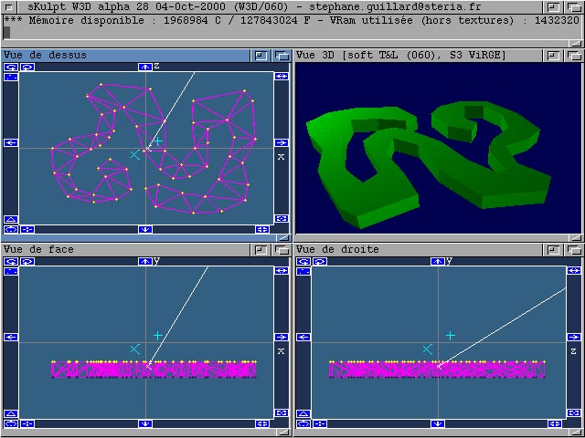
Note that the edges are not removed from the curve (so that you can reuse them). You can remove them by the "edit > remove selected edges" command.
This feature supports holes and more, but at this moment, the hole definition procedure is not available on the Amiga. Although I am not able to test this, I guess you should use a standard math library setup otherwise the triangulator may crash, as it is very sensitive to accuracy. If it crashes, it will give you an error message that you should report to me.
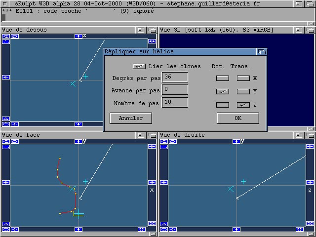
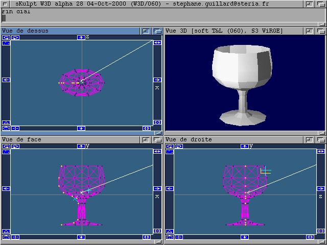
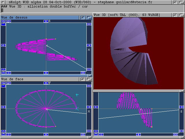
The dialog lets you choose whether the clones will be linked or not, if the clones are to be rotated and / or translated, the translation and rotation axes (which are smartly preset according to the 2D window which is active when you invoke the command), the angle in degrees per rotation step, the advance per translation step, and the number of steps.
Here is a sample of a curve, rotated and not translated to produce a glass shape :
Here is a sample of a triangle, both translated and rotated, to create a stairs shape :
Here is a sample of a cube set, translated and not rotated, to create a brick wall shape :
Window gadget commands
These icons enable you to :
 : rotate counter-clockwise or clockwise. This command only applies to the
selected vertices (of course, the edges and triangles they take part in will follow). This command also accepts
keyboard modifiers : clicking it while the left Shift key is pressed will double the angle (normally 1/40th
a turn, 1/20th when shifted).
: rotate counter-clockwise or clockwise. This command only applies to the
selected vertices (of course, the edges and triangles they take part in will follow). This command also accepts
keyboard modifiers : clicking it while the left Shift key is pressed will double the angle (normally 1/40th
a turn, 1/20th when shifted). and its 3 brothers : pan the visible "window". The 3D space is
projected onto the plane associated to each 2D window ; the 3D space is not finite in size, and you only see a
small rectangle window in this projection. You can move this window with the 4 pane gadgets. The 2D windows are
displaying the same 3D cube, so when you pan in any direction in any 2D window, the other windows will
"follow". This process is a but strange in the beginning, but anyone should quickly accommodate.
and its 3 brothers : pan the visible "window". The 3D space is
projected onto the plane associated to each 2D window ; the 3D space is not finite in size, and you only see a
small rectangle window in this projection. You can move this window with the 4 pane gadgets. The 2D windows are
displaying the same 3D cube, so when you pan in any direction in any 2D window, the other windows will
"follow". This process is a but strange in the beginning, but anyone should quickly accommodate. : center the 2D views on the main cursor position
 and
and  : add points and edges /
triangles. You can add points anytime. Adding edges and triangles is done the following way : if there is no
selected vertices, a triangle is added between the 3 cursors. If only one vertex is selected, nothing is done.
If 2 vertices are selected, an edge is added between them. If 3 vertices are selected, a triangle is added
between them. If more than 3 vertices are selected, nothing is done.
: add points and edges /
triangles. You can add points anytime. Adding edges and triangles is done the following way : if there is no
selected vertices, a triangle is added between the 3 cursors. If only one vertex is selected, nothing is done.
If 2 vertices are selected, an edge is added between them. If 3 vertices are selected, a triangle is added
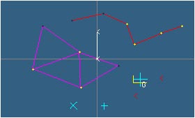
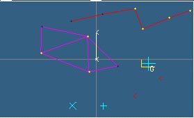
between them. If more than 3 vertices are selected, nothing is done. : this is the grabber tool de/activator. When you click it, it toggles the
grabber tool. When the grabber tool is active, it displays as a 'G' near the main cursor ; all relative moves of
the main cursor (when you drag it in a 2D window) will be applied to the selected vertices (and of course, the
edges and triangles they take part in will follow). Sample pictures above show this : on the left, we just
activated the grabber, and on the right we moved it up a bit ; only the yellow vertices have been affected :
: this is the grabber tool de/activator. When you click it, it toggles the
grabber tool. When the grabber tool is active, it displays as a 'G' near the main cursor ; all relative moves of
the main cursor (when you drag it in a 2D window) will be applied to the selected vertices (and of course, the
edges and triangles they take part in will follow). Sample pictures above show this : on the left, we just
activated the grabber, and on the right we moved it up a bit ; only the yellow vertices have been affected :
 and
and  : zoom in / out. Same
principle as panning.
: zoom in / out. Same
principle as panning. : I've forgotten about this one. It was in the original Sculpt, but I
don't remember its use, and live without it. If anyone wants something useful, just ask.
: I've forgotten about this one. It was in the original Sculpt, but I
don't remember its use, and live without it. If anyone wants something useful, just ask.
Keyboard commands
| Ctrl D | Magic cookie ! Same time demo as by menu command. |
| Enter | create triangle (same as menu entry or window gadget) |
| ESC | Rearrange the windows |
| Del | delete selection |
| < | Unselect all |
| > | Select all |
| ! | garbage collect (suppress holes in the data structures. Will be automatically done in all necessary cases) |
| Space | unselect all tools |
| c | Curve tool |
| f | Modify selected faces/material association |
| g | Grabber tool |
| i | Invert selection |
| k | Select linked nodes |
| l | Modify lamp properties |
| m | Modify material properties |
| o | Position the observer |
| p | Add point |
| q | Finish current curve |
| s | Selector tool |
| t | Position target |
| u | Unselector tool |
| x | Extrude tool |
| z | insert a break marker in the trace window, indicating the available memory status |
Sample workshops
To be written.
To do
Tech notes regarding the Amiga version
Rendering without a 3D graphics board could be done (given the relative conceptual simplicity of Warp3D), but the fill rate would be so slow with a 68K that it would seriously hurt...
Here are the optimization schemes used in sKulpt on the Amiga to reach an acceptable (from my point of view) performance level :
- the 2D windows are triple-buffered. For each 2D window, the 3rd buffer contains all (points, edges, and triangles) except cursors, axis, camera, target and camera/target link. It gets blitted into the 2nd only when a change is made in these elements. The 2nd is redrawn from the 3rd each time you move a cursor or camera etc. ; then it gets blitted into the window, to avoid flicker. This burns a lot of GFX board memory, but otherwise things are visually horrible because of flicker. There is only one 2nd buffer, shared among the 2D windows, to limit the burn rate of GFX board memory. The 2nd buffer is as large as the largest 2D window, and as tall as the tallest 2D window. All these buffers get reallocated each time the 2D window sizes are adjusted (so that if you want to have a large 3D window, you can reduce both the 3 2D windows to limit their GFX board memory usage).
- The 2D windows are simple refresh windows, so that Intuition does not handle its own buffer for each of them. This is to avoid burning useless GFX memory. SKulpt gets refresh queries from Intuition and handles them so that the windows get redrawn when they are resized or partially or fully undisclosed.
- The 3D window is double-buffered, to avoid flicker. It is also a simple refresh window. There is a 3rd memory buffer associated to the 3D window : the Z buffer. Of course, there is no Z buffer associated to the 2D windows.
- All these buffers (4 x double, 1 x triple, 1 x z + screen buffers) eat a lot of GFX board memory, something like 1 meg at 640x480, 2 meg at 800x600, and 3,6 meg at 1024x768, for the default window sizes. Take care, if your workbench also eats memory. Typically, with a 1024x768 15 bit WB on a CV64/3D with a backdrop picture, I would advise not going above 800x600, and even at 800x600 things may be tight. Symptoms are windows not fully refreshed and error messages like "... lock bitmap problem..." or "... lock hardware problem...". Warp3D and CybergraphX theoretically automagically handle flushing bitmaps and textures between non-GFX board RAM and GFX board RAM, but it has its limits. Also, one side effect of GFX board RAM exhaustion is that textures won't be uploaded into the GFX board, resulting in textured triangles not rendered. You don't get error messages for this one, since Warp3D automatically manages textures.
- The trace window is never redrawn. Neither Intuition nor sKulpt maintains a buffer of its contents (this is a simple refresh | no care refresh window). This is to avoid burning useless GFX RAM also. If you want to watch traces, put the trace window in front and size it accordingly or give a look in the shell startup window on the WB, which should hold a copy of all traces so that you can review them.
- All drawing operations are done using the 3D chip, even 2D ones in 2D windows (points, lines, surface filling). In fact, everything you see in the 2D windows except text and border gadgets is drawn with 3D primitives. It is the only way I've found to speed things up. Graphics.library calls are so slow that the 2D window refresh is unbearable when done with them, even on a top class machine (PPC is even worst in this case, since it has to call 68K code for each render call).
- Transform and Lighting are of course software processed, since until I see a GeForce in my Amiga, I have to provide code to transform 3D coordinates and lighting into screen coordinates and colors for each vertex. I try to optimize this to the max., and on the PPC it has very acceptable performance even on complex scenes.
- Clipping is partially software, partially Warp3D. Warp3D clipping is very slow, specifically when a triangle largely overlaps with render surface borders (in which it can even hang). In software, I eliminate all completely off screen triangles, and I also do a camera to triangle distance clipping. I rely on Warp3D to split the triangles across borders.
- When dragging something, the 2D windows only display vertices (no edges or triangles etc.) to speed up things. Even further, the 2 other 2D windows might not get refreshed at all.
- Most main variables are in static tables rather than in dynamically allocated spaces, to avoid reallocation and traversing. Most variable handling is de referenced using pointers at all levels, to avoid recalculating table indexing in loops. It uses more stack, but is also much faster.
- Same for implicit object construction/destruction and dynamic allocations : avoided to the max.
- In terms of compilation optimization, the StormC compiler optimizer is seriously broken above level 2 in 68K mode, and above level 0 in PPC mode (the produced executable simply does not run). Thus 68K code is optimized at level 2 (which does not speed much) and PPC code is not optimized at all. I'm frustrated not to be able to use the optimizer, and place much hope in the soon to be released StormC 4 package, which relies on GCC and should provide strong optimization features. I expect noticeable executable size reduction and maybe 20 to 40% overall speedups from even the simplest optimization levels.
- On 68K and PPC : the 68K is calculation power-limited, as is shown by camera or object dragging in medium complexity scenes (I talk about a 50 MHz 68060). Thinking about a 68K software rendering process (either as a Warp3D driver or as a direct application feature) is nonsense to me. The PPC is WAY faster, something like 10x a 50 MHz 68060 from the calculation-intensive application user (I talk about a 233 MHz 604 E). What would then make sense is to delegate software rasterization to the 68K from the PPC side... Two limiting factors in the PPC field :
- Wait() GetMsg() ReplyMsg(), loops, which rely on 68K code. Intuition messages can only be caught and replied to by the 68K, so from PPC software, you go to 68K each time you want a message from Intuition. This implies the famous "processor switch". The solution to this (not yet implemented in sKulpt) is to do a Mixed Binary executable, in which the main() from the 68K code :
- creates a PPC/68K shared message port,
- launches asynchronously the PPC code which itself waits on this port,
- waits for the Intuition messages, and feeds them to the shared port.
- ClipBlit() calls, which are necessary to double buffering, and which are also on the 68K side. Two solutions to this : either rewrite some ClipBlit () like on the PPC, or use a symmetric scheme to the one exposed above for intuition message handling.
This both faster (on calculation side) and slower (on Intuition and clipblitting side) behavior of the PPC version is well shown when you load a big scene and move the camera around it : you are almost not slowed by calculation, but by the overhead of going to 68K, as the camera moves at the same speed as when you don't have any object ! Kudos to the Jordan and Frieden team because when you run WipeOut in windowed mode, you face the same problems but it does not feel sluggish. Wow.
- The ViRGE chip on the CV64/3D (or it's Warp3D driver) has several limitations : 4 megs of GFX ram is not that much ; it does not texture lines and points (thus wireframe or point rendering is not textured) ; it does not handle properly triangle coordinates with X < 0 ; it is not very fast (but I'm still VERY happy to be able to run 3D software on this board).
- The Permedia 2 chip on the B|CVPPC (or its Warp3D driver) also has limitations : it is not handle LineLoops properly (the closing segment is not drawn properly) ; clearing the Z-buffer can not be done at any time.
- Both chips have a limited fill rate. Far better with the Permedia 2, but not even 1/100th the one of my GeForce in my PC. Shame ! On the PC, none of the above optimizations were required in the Direct3D version of sKulpt, which is orders of magnitude faster than even the PPC version running on the Permedia2 ...
- Eagerly waiting for the Predator or A4K Mediator to have a modern GFX board (I would even like to write the Warp3D / CGFx driver for the GeForce 2 Ultra !), and can't wait for the G4 on top of this.
- SKulpt is written on the Amiga using the only modern and productive developer's environment : StormC 3 together with GoldED V6. This gives you something almost comparable to Visual C++, a bit slower, but still very usable, and effortlessly able to make 68K and PPC executables out of the same source code, an efficient source debugger completely integrated with the editor, and much more. Only missing a good optimizer !
Author

I am a software engineer working in a subsidiary of a large and great French IT firm, Steria.
Over all, sKulpt is one of an Amiga-fond programmer's projects, which aims at maintaining me fluent with modern programming techniques and environments on the Classic Amiga, a machine I consider superior to others, due to the expandability of all its aspects and design concepts. Do you know a machine and its OS from the mid-eighties, which can run on the Web, with RTG, 3D graphics, 16-bit sounds etc. and still provide excitement to many of us ? Apart from the Classic Amiga, I don't see. Try expanding a Macintosh 512K, an Atari 1040ST or a PC/AT etc. to reach this level of functionality.
Fond, I am of the Amiga (I own and use a 500+, a 1000, various 2000 and 2 4000s), but also of the Apple //s (a //e, a IIc, a IIgs), a Mac SE/30 (brilliant integrated machine), a NextCube, an Atari 1040 ste, and a PC (plus various other less important 8 bit machines). Hours, many (thousands since the early 80's) I spent on these keyboards, diving in system software and writing application software and system tools. Smart Motorola CPU's tend to be the heart of smart machines...
Another Amiga project of mine is AmiVNC (available on Aminet), a VNC server for the Amiga, which should get a deep rework before the end of the year (involving porting from SAS/C to StormC).
Thanks
Hardware : Commodore original design team, special mention to Dave Haynie, VillageTronic, Phase 5, GVP, Janal crew
Software : authors of the jewels : MUI, MCP, SAS/C, Aztec C, Storm C, WarpOS, Warp3D, Picasso96, Cybergraphics, NetConnect, AmiTCP, Miami, IBRowse, Yam, AmIRC, Microdot, MakeCD and a few other
Legalese
I hope no one will find a copyright infringement in all this stuff, as its only purpose is have fun with open source software, experiment and share, and bring life back into an ancient model of the smart software without having ripped any single of its source line.
" The author of this software can not be pursued in any case …"
" Use at your own risk …"
" Make backups … "
" Please if you propagate this software, do so using the original archives …"
" Send me back your enhancement ideas and source code …"
" Have fun …"
DownLoads |
Binaries | Sources | Documentation | Localization | Example scenes |
|---|---|---|---|---|---|
| 68000 |  |
|
|
|
|
| 68020 | |||||
| 68030 | |||||
| 68040 | |||||
| 68060 | |
||||
| PPC / WarpOS | |
||||
| x86 / Windows |  |
||||